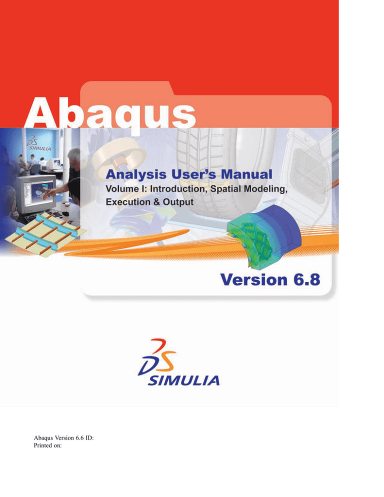
Please check your input data to see if they meet both criteria as explained in MATERIAL DATADEFINITION section of Abaqus Analysis User Manual. The Abaqus documentation is provided in portable document format (PDF) on the documentation DVD as. They do not appear in the PDF version of the manual. Msc adams user manual. Noby bs2 manual arts instruction on gt.bet4yy.site.
HTML is the primary format for the Abaqus documentation. The HTML manuals. This section contains information on using the Advanced Search options. Execution procedure for fetching sample input files. Products.
| Author: | Kagall Daigar |
| Country: | Denmark |
| Language: | English (Spanish) |
| Genre: | Travel |
| Published (Last): | 20 June 2015 |
| Pages: | 451 |
| PDF File Size: | 8.53 Mb |
| ePub File Size: | 13.93 Mb |
| ISBN: | 620-7-99107-697-3 |
| Downloads: | 13890 |
| Price: | Free* [*Free Regsitration Required] |
| Uploader: | Dolabar |
By default, the search function matches the exact spelling of the search term or phrases.
By default, the search function locates words in All searchable text. This manual describes the Abaqus Scripting Interface, dochmentation is an application programming interface API to the models and data used by Abaqus. A mass diffusion docjmentation MPCs multi-point constraints allow constraints to be imposed between different degrees of freedom of the model. The use of Fick’s law also introduces temperature-driven mass diffusion since a Soret effect factor is calculated automatically.
Abaqus documentation should be installed on at least one computer on your network.
The units of the Soret effect factor are. Element integration point variables: These values affect only field-variable-dependent aabaqus properties, if any.
Abaqus Installation and Licensing Guide.
Mass diffusion analysis
If the number of hits seems excessive, you can add more words to the Search text field or select another option to abaqux the search. By default, the analysis will end when the given time period has been completed.
To request an Abaqus license file, contact your local sales office. For the definitions of a general release, an extended functionality release, and a maintenance delivery, see the Abaqus Glossary. Therefore, when the mesh includes documfntation materials that share nodes, the normalized concentration is continuous across the interface between the different materials.
Abaqus User Subroutines Reference Manual.
Optionally, a Soret effect factor and a pressure stress factor can be defined to introduce mass diffusion caused by temperature and pressure gradients, respectively. Documentarion manual describes the components and organization of the Abaqus GUI. This section contains information on using the Advanced Search options available in the Abaqus HTML documentation in both the book and collection windows.
FixedIncrement size: The diffusion problem is defined from the requirement of mass conservation for the diffusing phase: Keyword parameters, which can be optional or required, provide additional information concerning the keyword.
It also discusses the utility routines that can be used when coding subroutines.
Execution procedure for fetching sample input files
This manual contains benchmark problems and analyses used to evaluate the performance of Abaqus; the tests are multiple element tests of simple geometries or simplified versions of real problems. By default, no backup versions are created.


Predefined temperatures, equivalent dochmentation stresses, and field variables can be specified in a mass diffusion analysis. The list of available search filters appears when you click the Limit search to menu button. Spurious oscillations due to small time increments. It is generally useful to look for relevant examples in this manual and to review them when embarking on a new class of problems.
Click Advanced Search in the navigation frame to display the Advanced Search window. It may be useful to run these problems when learning to use a new capability. Use the following options: Abaqus Scripting User’s Baaqus. To select the word form or derivative words that the search function will match, use the Match parameter.
Abaqus User Manual 2019 Pdf
Such values can be specified as functions of time.
Software Installation for Windows
GUI text includes buttons and labels. Use the following option to define a nonuniform distributed concentration body flux: To define nonuniform distributed concentration fluxes, the variation of the flux magnitude throughout a step can be defined in user subroutine DFLUX. The options for the upgrade utility are: The disk space used for installation will be charged against absqus account of the owner of the Abaqus installation directory.
Abaqus Scripting Reference Manual. The Abaqus keyword interface is used to model examples similar to those included in Getting Started with Abaqus: Using Abaqus Online Documentation.
Abaqus 6.9 Supported Platforms & Products
If you choose fixed time incrementation, fixed time increments equal to the size of the user-specified initial time increment,will be used. Use the following input to define a concentrated concentration flux at a node: Abaqus Scripting Interface object: User-defined Use the following input to abaqjs a nonuniform distributed concentration surface flux: It is the basic reference document for the Abaqus Interface for Moldflow.
Use the following input to define a distributed concentration flux acting on entire elements body flux or just on element faces surface flux:. Mass diffusion behavior is often described by Fick’s law Crank, Values in the results documentstion are ignored at nodes that exist in the mechanical analysis but not in the mass diffusion analysis, and the pressures at nodes that did not exist in the mechanical analysis will not be set by docu,entation the results file.
Abaqua manual contains a complete description of each command in the Abaqus Scripting Interface. This manual contains a complete description of all the user subroutines available for use in Abaqus analyses. This manual provides a command reference that lists the syntax of each command in the Abaqus GUI Toolkit. Abaqus Analysis User’s Manual.
Related Posts (10)
View
91Download
8
Embed Size (px)
Text of Abaqus Tutorial 02
H. Kim FEA Tutorial
1
ABAQUS/CAE Tutorial: Analysis of an Aluminum BracketHyonny Kim
last updated: August 2004
In this tutorial, youll learn how to:1. 2. 3. 4. 5. 6. Sketch 2D geometry & define part. Define material properties. Apply loads and boundary conditions. Mesh. Run analysis. View results.
H. Kim FEA Tutorial
2
Helpful Tips Before Getting StartedUse Exceed 9.0 or equivalent PC terminal software. HELP Online help manuals: abaqus_aae doc & - there is a book for CAE: ABAQUS/CAE User's Manual. Context sensitive help is also available within CAE. CAE creates the .inp file which you can edit and run by the command line, or you can submit jobs from within CAE. Other files are .cae (CAE model file), .odb, .dat, .log, .msg, and .sta. The .dat is the text output file that will contain results. The .odb file is the binary output file that will be read during post-processing to view graphical results. The .log file keeps a text record of all processes and is useful for checking the status of the analysis. The .msg lists the progress of the analysis, as well as provides some messages about why an analysis might have crashed (this information is often within the .dat file as well). The .sta file is a summary of the information contained in the .msg file, and is useful for monitoring the status of long-running jobs during their computation. MOUSE Use of the Mouse: button 1 (left) is select, button 2 (right) gives menu, button 3 (middle, if available is enter or done) multiple items can be selected by: dragging a window or holding the SHIFT key while picking items can be de-selected by holding the CTRL key.
H. Kim FEA Tutorial
3
ABAQUS/CAE: Getting Started, Create Part To run ABAQUS/CAE, first go to the directory you wish your files to be located, then type: abaqus_aae cae or /usr/site/aae/bin/abaqus_aae cae click Create Model Database In the Module dropdown box, select Part (this takes about 30 seconds for the program to initialize) Note the locations of: Tool Bar, Menu Bar, Toolbox Area, Prompt Area. These will be referred to repeatedly in the future. In the Toolbox Area, click Create Part button. The Create Part window will pop up. Enter in name, e.g., bracket Under Modeling Space, choose 2D Planar Base Feature, Shell Approximate size: 20 click Continue
H. Kim FEA Tutorial

4
Sketch Part The window will change to that shown at right. Note the buttons pointed out. Buttons with a dark triangle will provide more button choices when clicked and held. Try it. Float your mouse pointer over buttons, it will give a pop-up description. Context-Sensitive Help is available. Click the help button, then the item you want more info on.
1.
Click Create Lines button. Note it is highlighted when active. In prompt area, enter in the coordinates:1. 2. 3. 4. 5. 6. 7. 0, 0 8, 0 (it is ok if point is be out of view) 8, -12 5, -12 5, -3 0, -3 click on point 1 (box will appear on it). Finished product will be yellow outline of the bracket. Click Auto-Fit View button to re-scale image. The other buttons adjacent to this one will adjust panning, rotation, and zoom. Try them out. Dynamic viewing with mouse buttons by holding CTRL + ALT on right side of keyboard. Try it.
2. 3.

Click Create Circle button. Enter 6.5, -1.5 for center, and 7.25, -1.5 for perimeter point. Click Create Fillet button (go to next page)
H. Kim FEA Tutorial
5
Sketch Part contd.3. contd enter 1.0 for fillet radius in the Prompt Area, hit enter, then Mouse click on inner two lines when prompted. The Create Fillet button should still be highlighted. Click this again to get the screen shown below left. Click the Done button in the Prompt Area at the bottom of the screen. You now are returned to the Part Module screen. This should look like the screen below right. Note different tool buttons shown in the Toolbox Area.
H. Kim FEA Tutorial
6
Partition Edge Click the Partition Edge: Enter Parameter button. In order to get this button, you need to click and hold over the line partitioning tools button note the small dark triangle in the lower right corner indicates that this is an expanding button. You will be prompted to select an edge, select the far righthand edge of the bracket. Click Done. In the Prompt Area, enter in value of 0.25 for the Normalized edge parameter. Click the Create Partition button to finish. You will see a large dot onefourth of the way up the edge of the bracket. This partitioned edge will be used later for applying a uniform load.
H. Kim FEA Tutorial
7
Saving and Defining Material Properties Save your work: in the Menu Bar, click File, Save As. Under Selection, enter a name at the end of the path, e.g. bracket. Click OK. From now on, you can just click the blue floppy disk icon in the Tool Bar. Save often!!!
1.
Change Modules. In the Module drop-down box beneath the Tool Bar, select Property. Click Create Material Buttonenter a name, e.g. Aluminum, select Mechanical --> Elasticity --> Elastic enter 10e6 for Youngs Modulus, 0.3 for Poissons Ratio. click OK If you want to modify the material, click the Material Manager button to the right of Create Material, select the material by name and click Edit, or click Dismiss to leave without making any changes.
H. Kim FEA Tutorial
8
Assign Properties to Regions of Model2. Click Create Section Button enter a name, e.g., plate choose Solid and Homogeneous click Continue select the material Aluminum (or what ever you named it, there should be only one to choose from) in the drop down box enter Plane stress/strain thickness: 0.05. Click OK. you will be prompted to select a region. Click on the part. Click the Done button in the Prompt Area at the bottom of the screen. The Assign Section window will pop up. Select the Section Name you wish to assign to this region (there should be only one which youve previously named, e.g., plate) click OK.
3.
Click Assign Section Button
H. Kim FEA Tutorial
9
Instance Part Change Modules. In the Module drop-down box beneath the Tool Bar, select the Assembly. note, the Canvas (main working graphical window) will be blank.
Click the Instance Part button. The Create Instance window will pop up. Select the part you wish to instance, e.g., the part we named bracket previously. A red outline of the bracket will show. Click OK.
H. Kim FEA Tutorial
10
Step Change Modules. Select the Step module. Click the Create Step button. Create Step window pops up enter a name use the default name Step-1. be sure Procedure type is set to General, and Static, General is highlighted in the list. Click Continue.
Edit Step window pops up, with the Basic tab active. enter in a Description, e.g., apply loading under Increment Size, enter value of 0.1 for Initial. Leave the rest the same. Full load corresponds to an Increment value of 1 (when Time Period is set to 1 under the Basic tab). Setting Initial to 0.1 forces ABAQUS to start the analysis by applying 1/10 of the full load. This can also be left to default 1 value and the software will auto-select. click OK.
Click the Incrementation tab.
Abaqus User Manual 2016
H. Kim FEA Tutorial
11
Load Change Modules. Select the Load module. Click the Create Load button. the Create Load window pops up. enter a Name, e.g., Load-1 is the default name be sure Step-1 (or what name you have given it) is selected in the Step drop down box. be sure Mechanical is selected in Category under Type for selected step, choose Pressure click Continue Upon prompting to Select surfaces, mousepointer click on the lower portion of the right edge of the bracket, the region we partitioned previously. It will highlight red. click Done. in the Edit Load window that pops up, be sure to have Distribution set to Uniform, enter value of 1000 in Magnitude, and be sure that (Ramp) is selected under Amplitude. This is a 1000 psi traction. click OK. You should get the image shown to the right. If your arrows are in the wrong direction, you need to go back and be sure to specify a negative pressure.
H. Kim FEA Tutorial
Abaqus User Manual 6.13
12
Boundary Conditions Click the Create Boundary Condition button. the Create Boundary Condition window pops up. enter a name, e.g., fixed edge under Category, be sure that Mechanical is selected. under Type for selected step, choose Displacement/Rotation click Continue. upon prompt to select regions, mousepointer click on the upper left vertical edge of the bracket. It will highlight red. click Done. Edit Boundary Condition window pops up. be sure Uniform is selected in Distribution. check-mark (click) boxes for u1 and u2, and leave the default values of 0. click OK. You should get the image shown to the right
H. Kim FEA Tutorial
13
Seed Mesh Change Modules. Select the Mesh module. Click the Seed Part Instance button. This is an expandable button. There are many other functions within this button that are useful for controlling mesh size. In the Prompt Area, enter a Global element size value of 0.5. Hit enter and you will see circular symbols indicating nodal locations along the part edges.
Abaqus User Manual 6.14 Pdf
Click the Assign Element Type button. the Element Type window pops up. choose Standard in Element Library Plane Stress in Family Linear in Geometric Order within the Quad tab, choose Reduced Integration in Element Controls. Leave everything else at default values. the text in the lower box should indicate a CPS4R element identification. This is a 4-node reduced integration quadrilateral element. click OK.
Abaqus User Manual 2018 Pdf
H. Kim FEA Tutorial
Abaqus User Manual 6.12
14
Abaqus User Manual Umat
Mesh Click Mesh Part Instance button. Note this button has many other functions within it (